Fixing a reject mains voltage sensor
Introduction
A little over a year ago I purchased a mains voltage sensor module from from a local reseller of cheap electronics from China (eparnters) for $4.99 NZD. This is a small transformer (model ZMPT101B) with an amplifier on a small PCB.
Yesterday I returned to working on the project I bought this for, and after wiring it up, I found no signal on the output pin.
Sadness 😭
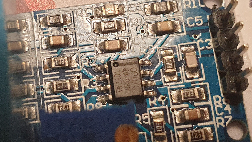
Yeaaaaaah… that’s the wrong part.
No signal
After a few minutes of frustration watching the scope and adjusting the gain pot, I pulled up the data-sheet for the OP07 op-amp on this board, and started probing the pins with my DMM and noting down voltages.
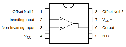
Pin-out for the OP07 op-amp
What I found made no sense. My first thought was maybe the package was soldered the wrong way around, so I redid my notes with the 180 degrees rotation, but that still didn’t make sense…
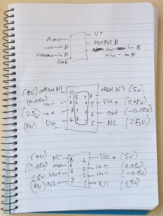
Confused notes and atrocious hand-writing…
Getting a bit desperate, I started doing web searches for the ZMPT101B module, and came upon this site where I saw the following image of the same module.
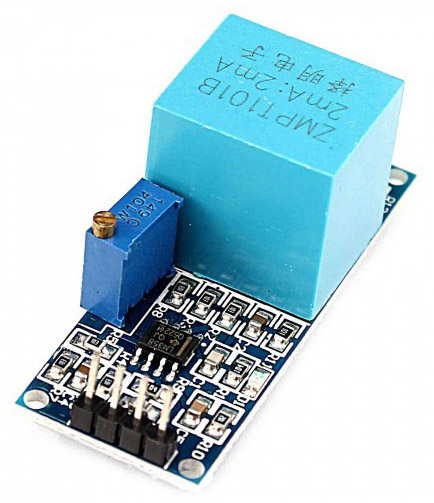
Same module, different op-amp?! electropeak
Notice this module looks identical but the op-amp is an LM358. Pulling up the data-sheet, I realised the measurements would make sense if the dual op-amps of the LM358 were chained together:
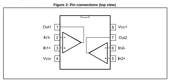
Pin-out for the LM358 dual op-amp package
The fix
So… let’s fix it. I picked up an LM358 at Altronics…
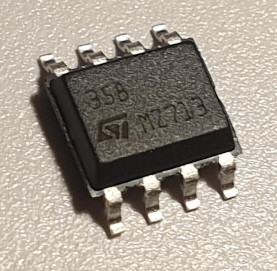
This is the correct chip!
…and set about removing the OP07 with some hot air:
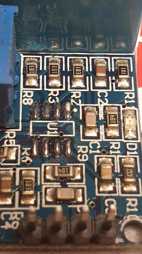
PCB after removing the OP07 SOIC-8 package
Getting the orientation correct for the ST Micro LM358 SOIC-8 package was a little tricky for me. Here is the drawing:
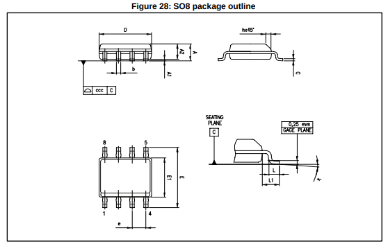
ST Micro LM358 SOIC-8 package drawing from the data sheet
Note the slighly more beveled edge on the pin 1-4 side. It is actually visible in the photo if you look real close:
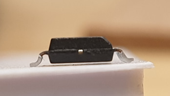
Orientation indicated by the beveled edge
Some more heat and solder and the new op-amp is installed:
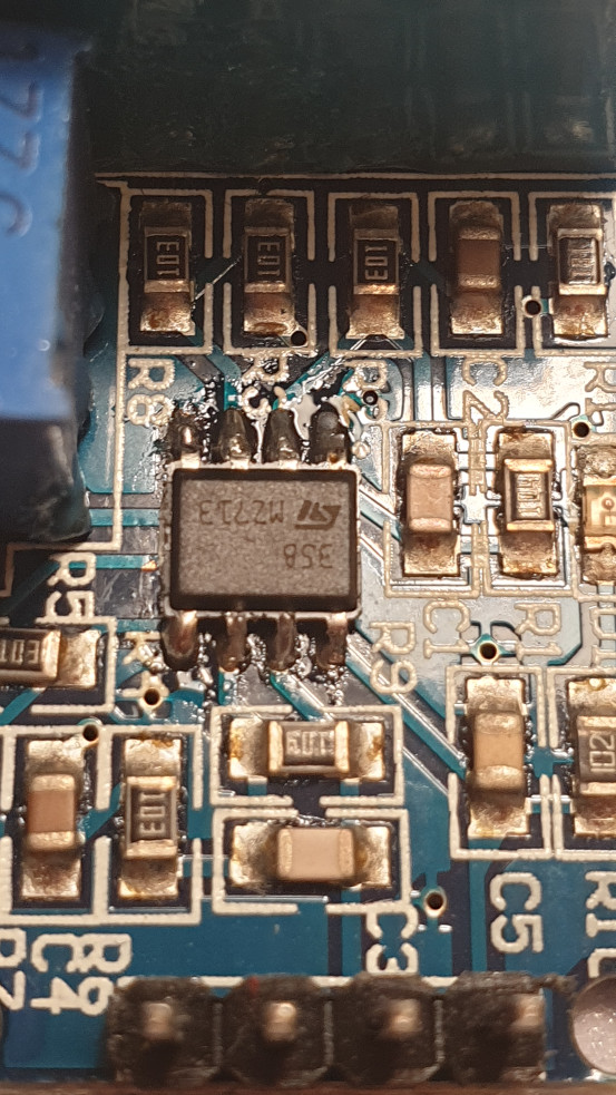
ZMPT101B with correct (LM358) op-amp installed
And happily it worked! I immediately got a signal, and it was easy to adjust the gain to prevent clipping with the scope attached::
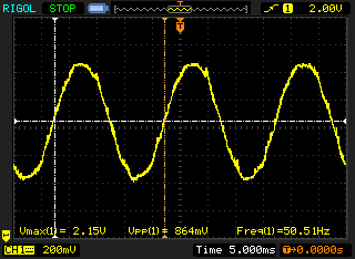
That sweet 50Hz hum!
Conclusion
In countries where buying hobby electronics supplies from the likes of Adafruit and Sparkfun incurs expensive shipping, online resellers buy bulk items on alibaba.com and re-sell them in-country with a stiff mark-up for impatient people (like me).
I suspect the factory (probably a CM using spare capacity to churn out these modules) made a mistake and loaded the wrong reel of op-amps into their pick-and-place machine. This might also have been a grey-goods (i.e., workers running the line at night) situation. Either way, the modules were faulty and probably offloaded at a steep discount to the NZ reseller (more profit!).
The seller probably didn’t know any better (I wouldn’t expect them to test everything they resell) and I fixed the module anyway (and had fun doing that) so all is well that ends well.