Calibrating a Ruideng RD6006 power supply
Introduction
Last year I bought a Ruideng RD6006 variable power supply. It arrived poorly calibrated but fortunately the manufacturer provides Windows software and instructions for re-calibration. Out of necessity I installed the software in a virtual machine (in Virtualbox) and bridged the serial port on the host to let it talk to the hardware.
The calibration procedure involves finding the correct y intercept and coefficient (slope) for a linear function that maps the raw internal ADC sampling of two sets of voltage and current, to real values. Getting it perfect (or as close to perfect as possible) is a little fiddly.
After some tinkering I though it would be much better to ditch the Windows software and make my own tools. Other folks had already documented the modbus control registers for the RD6006 and there is an easy to use Python module for it.
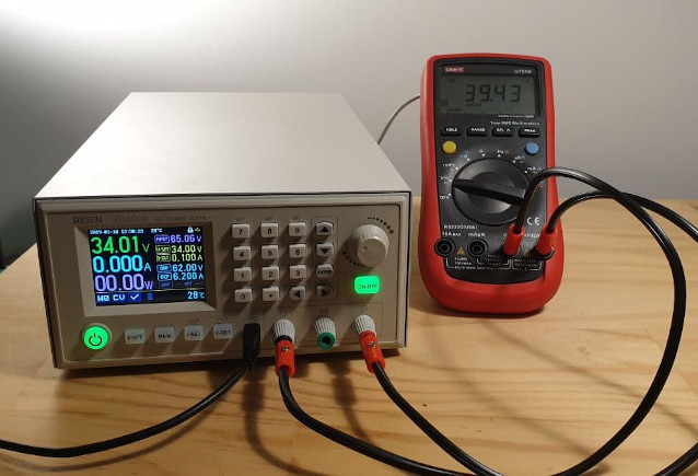
Calibration setup showing the obvious problem.
Reverse engineering calibration adjustment
The first tool I wanted was something to read and set the eight calibration registers (0x55 through 0x62) so that I could ditch the VM. This appeared to work at first, but the new calibration values wouldn’t stick - they reverted to the old values if the power supply was turned off. I figured there must be some commit command, so I worked out a setup for sniffing the serial port. The first step is to have the VM open a UNIX domain socket instead of the character device file, i.e., instead of /dev/ttyUSB0, to open something like /tmp/vboxserial0. Next, I had socat bridge between the UNIX socket and a listening TCP socket:
socat unix-connect:/tmp/vboxserial0 tcp-listen:8001
Finally, I had another socat process connect the real serial port to the TCP port and also echo the binary data as hex to stdout:
socat -xd /dev/ttyUSB1,b115200,raw,echo=0 tcp:localhost:8001
With some careful timing and patience, I narrowed down on a command issued when the PC software saves (previously written) calibration registers to NVRAM:
> 2020/04/01 15:44:07.547249  length=8 from=520 to=527
 01 06 00 36 15 01 a6 94
Happily this did the trick:
def write_calibration_registers(rd, regs):
    set_panel_locked(rd, True)
    for address, value in zip(range(55, 63), regs):
        print("Writing %d = %d" % (address, value))
        rd._write_register(address, value)
    # magic register/value to commit cal registers to nvram
    # 01 06 00 36 15 01 a6 94
    # 0x54 = 36
    # 0x1501 = 5377
    rd._write_register(54, 5377)
    set_panel_locked(rd, False)
    print("Done.")
Calibration sweep
The second tool I wanted was something to sweep across the output voltage range of the power supply while logging the actual voltage measured via my multi-meter:
$ ./sweep.py
Usage ./sweep.py [PSU_SERIAL_PORT] [DMM_SERIAL_PORT] [OUTPUT_FILE]
$ ./sweep.py /dev/ttyUSB0 /dev/ttyUSB1 before
RD6006 or other detected
0.000000        0.010000        0.000100        0.009900
1.000000        1.000000        1.156400        -0.156400
2.000000        2.000000        2.317000        -0.317000
<snip>
60.000000       56.050000       64.990000       -8.940000
61.000000       56.050000       65.000000       -8.950000
62.000000       56.050000       64.990000       -8.940000
The idea is to check the calibration by plotting the result gnuplot:
gnuplot> plot \
    'before' using 1:2 with linespoints title "PSU display", \
    'before' using 1:3 with linespoints title "DMM V"
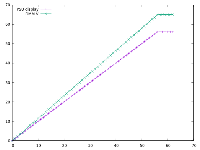
RD6006 output voltage sweep with poor calibration.
Now with the means to properly measure the effects to calibration adjustments, I used the first tool to iteratively align the two curves. For demonstration, this run shows switching from the “before” to “after” values:
$ ./calibrate.py /dev/ttyUSB0
RD6006 or other detected
Current calibration registers:
OUTPUT V ZERO    18
OUTPUT V SCALE   26770
BACK   V ZERO    19
BACK   V SCALE   14985
OUTPUT I ZERO    256
OUTPUT I SCALE   25278
BACK   I ZERO    78
BACK   I SCALE   14965

Enter new calibration registers:
OUTPUT V ZERO    [18]: 20
OUTPUT V SCALE   [26770]: 23205
BACK   V ZERO    [19]: 20
BACK   V SCALE   [14985]: 17290
OUTPUT I ZERO    [256]:
OUTPUT I SCALE   [25278]:
BACK   I ZERO    [78]:
BACK   I SCALE   [14965]:

Writing new calibration registers:
Writing 55 = 20
Writing 56 = 23205
Writing 57 = 20
Writing 58 = 17290
Writing 59 = 256
Writing 60 = 25278
Writing 61 = 78
Writing 62 = 14965
Done.

Reading back new calibration registers:
OUTPUT V ZERO    20
OUTPUT V SCALE   23205
BACK   V ZERO    20
BACK   V SCALE   17290
OUTPUT I ZERO    256
OUTPUT I SCALE   25278
BACK   I ZERO    78
BACK   I SCALE   14965

New registers were written successfully.
Running and plotting the sweep again, the voltage is reasonably accurate:
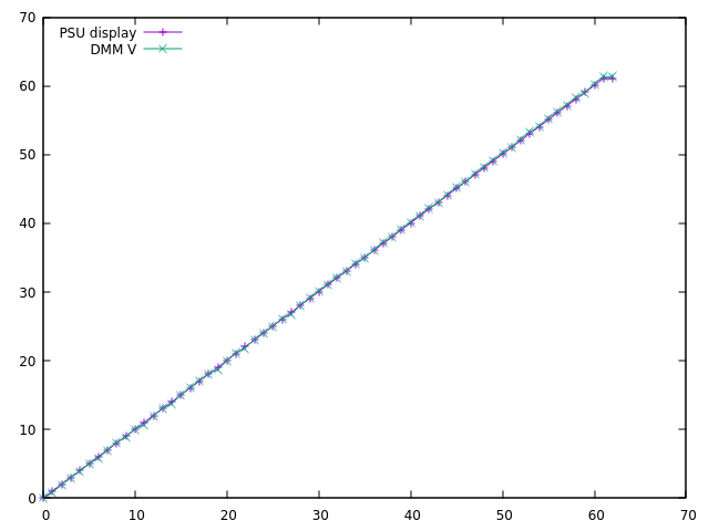
Result! Voltage sweep after re-calibration.
Conclusion
I’ve published my scripts (here) for others to use, and hopefully improve. Here is whats missing:
- Current calibration (I need a suitable load to do this).
- Support for output measurement with something other than the UNI-T 61e (perhaps using libsigrok to make it generic?).
- Some kind of error-minimising loop to perform auto-calibration.